Welcome to My Blog!
Before we dive into the content, I’d love for you to join me on my social media platforms where I share more insights, engage with the community, and post updates. Here’s how you can connect with me:
Facebook:https://www.facebook.com/profile.php?id=61576230391049
Now, let’s get started on our journey together. I hope you find the content here insightful, engaging, and valuable.
Table of Contents
Introduction
When you’re planning wiring for a commercial building, industrial plant, or data center, knowing how to do a proper Cable Tray Installation isn’t just a detail—it’s critical for safety, future scalability, and long‑term cost savings. A well‑designed cable tray layout supports your cables now and into the future, keeps them protected, and makes upgrades or troubleshooting straightforward. This guide is designed to walk you through every step of the process—from prep work to final inspection—so you get it right the first time.

Pre‑Installation Planning
Route Mapping and Site Preparation
Start with detailed building plans to map out cable tray routes, avoiding HVAC ducts, plumbing, and structural elements. Identify access points for future expansion.
Support Structure Design
Cable trays require properly anchored supports. Calculate support spacing based on tray type and load, and ensure brackets and hangers are appropriately specified for ceiling, wall, or under‑floor install.
Load and Weight Analysis
Factor in the total weight of cables, fittings, and accessories. Leave space for future additions and avoid overloading trays, which can cause sagging or compromise safety.
Compliance and Safety
Adhere to local wiring codes and industry standards for cable tray systems. Plan for access, clearance around live equipment, and proper grounding procedures.
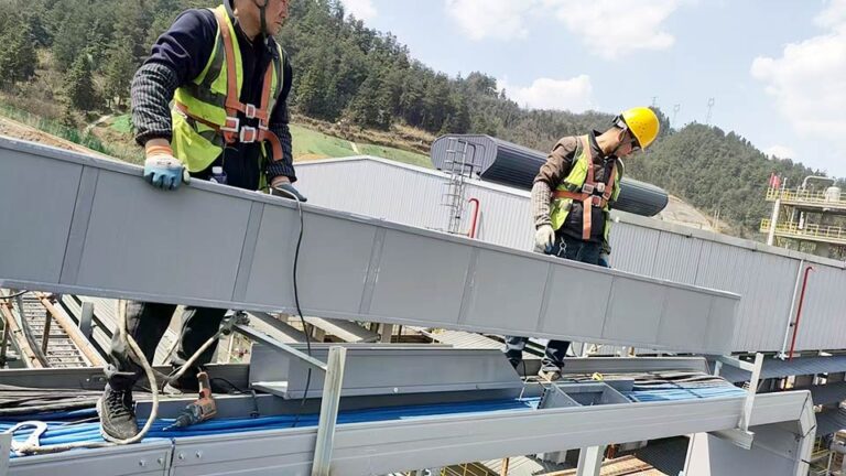
Step‑by‑Step Cable Tray Installation
Step 1: Base Support Installation
Mark installation points and secure hangers or brackets. Ensure they’re level and spaced correctly to support the load without mid‑span sag.
Step 2: Assembling Cable Tray Sections
Install ladder, perforated, or solid trays onto supports using appropriate joining hardware. Ensure transitions with bends, tees, and crosses are assembled with plated fittings and connecting bolts.
Step 3: Route and Bundle Cables
Place cables carefully into tray sections without exceeding fill percentage. Maintain bends above minimum bend radius to prevent insulation damage.
Step 4: Secure Cables Properly
Fix cables using compatible cable ties, clamps, or strapping. Leave sufficient slack to allow for thermal expansion and movement during maintenance.
Step 5: Bonding and Grounding
Ensure each tray section and fitting is electrically bonded, connecting to the grounding system. This prevents electrical shock hazards and interference.
Step 6: Final Checks and Testing
Perform a final inspection for alignment, support securement, cable fill limits, grounding continuity, and finish integrity. Document completed installation for future audits.
Design Considerations & Best Practices
Calculating Load Capacity
Compute total load from cables and hardware, checking that tray neutralizes bending moments. Over‑capacity leads to structural failure.
Rung Spacing and Cable Support
Standard rung spacing is 230–300 mm; smaller spacing helps in hosting low‑volume, delicate cables.
Bend Radius and Route Geometry
Design bends with large radius to prevent damage. Use 45° or 90° elbows, drop-outs, and pull‑points to simplify installation and future changes.
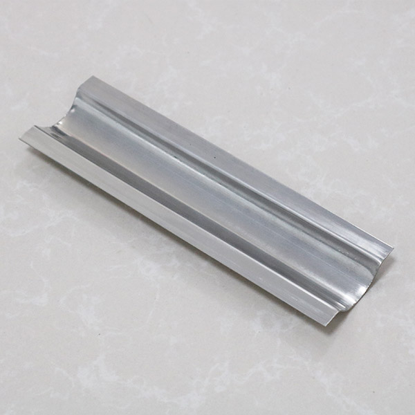
Material Selection for Environment
Choose galvanized steel, aluminum, stainless-steel, or fiberglass reinforced plastic (FRP) depending on exposure to chemicals, moisture, or extreme temperatures.
Expansion and Seismic Joints
Account for thermal expansion and building movement. Include expansion joints in long runs, especially over 30 m, and seismic bracing as required.
Cable Tray Installation Methods Comparison
| Installation Method | Typical Application | Advantages | Common Mistakes to Avoid |
|---|---|---|---|
| Wall-mounted tray | Indoor routing along walls | Saves floor space, good visibility | Improper anchor spacing, loose brackets |
| Ceiling-suspended tray | Warehouses, plants with high ceilings | Keeps floors clear, easy maintenance access | Inadequate hanger support or unbalanced alignment |
| Floor-mounted tray | Raised floors, data centers | Simple routing, easy to inspect | Poor protection from foot traffic or spills |
| Vertical riser tray | Between floors or control rooms | Efficient vertical cable transport | Overfilling or exceeding bend radius |
| Under-raised floor tray | Office spaces, server rooms | Hidden installation, noise reduction | Inadequate ventilation and overheating |
| Ladder tray with drop-outs | Power cables with heavy insulation | Excellent heat dissipation, strength | No radius control at drops, loose cable fittings |
| Wire mesh tray | Low-voltage or fiber optic cabling | Lightweight, flexible, easy to cut and adjust | Sharp edges if improperly trimmed, weak supports |
Common Installation Mistakes & How to Avoid Them
- Incorrect support spacing leads to uneven sag or tray failure.
- Overfilling trays limits cable cooling and complicates maintenance.
- Improper grounding can result in shock risk or EMI issues.
- Sharp bends or misaligned connectors create damage points or stress cables.
- Neglecting future growth leads to outdated, over‑packed pathways.


Routine Maintenance and Inspection
Scheduled Visual Check‑ups
Inspect quarterly for sag, corrosion, loose clips, cable bulging, or fill over‑capacity.
Cable Management Upkeep
Tighten ties, re‑bundle cables neatly, and update labels for all moved or newly added lines.
Tray Cleaning and Corrosion Control
Wipe dusty solid trays and inspect metallic trays for rust. Apply protective coatings as needed.
Documentation and Record‑Keeping
Maintain route maps, capacity tables, and change logs. These are critical for troubleshooting or adding circuits later.
Conclusion
A solid Cable Tray Installation is more than procedural—it’s strategic infrastructure that affects safety, maintenance, and adaptability. When you nail planning, support design, correct installation, cable management, grounding, and periodic checks, you create a system that performs today and welcomes expansion tomorrow.
If you’re planning a project or need expert help with design, material selection, or compliance, our team is ready to support you.
📩 Contact us today for custom cable tray solutions tailored to your use case and future needs.
FAQ
What’s the right hanger spacing for tray systems?
Typically ladders use 1.5–3 m spans; wire mesh uses 1–1.5 m; perforated trays often need 0.75–1.5 m spacing.
Can different tray types be used together?
Absolutely. Use transition fittings and ensure consistent grounding when changing between tray types.
Is grounding necessary for cable trays?
Check manufacturer specs, but factor in both initial load and estimated future increments—never push to limits.
How much load can a tray carry?
Check manufacturer specs, but factor in both initial load and estimated future increments—never push to limits.
How do I manage bends in tray layouts?
Use smooth, factory bends and allow pull points for cable pulling; adhere to minimum bend radii per cable specs.